Frequency converter harmonics
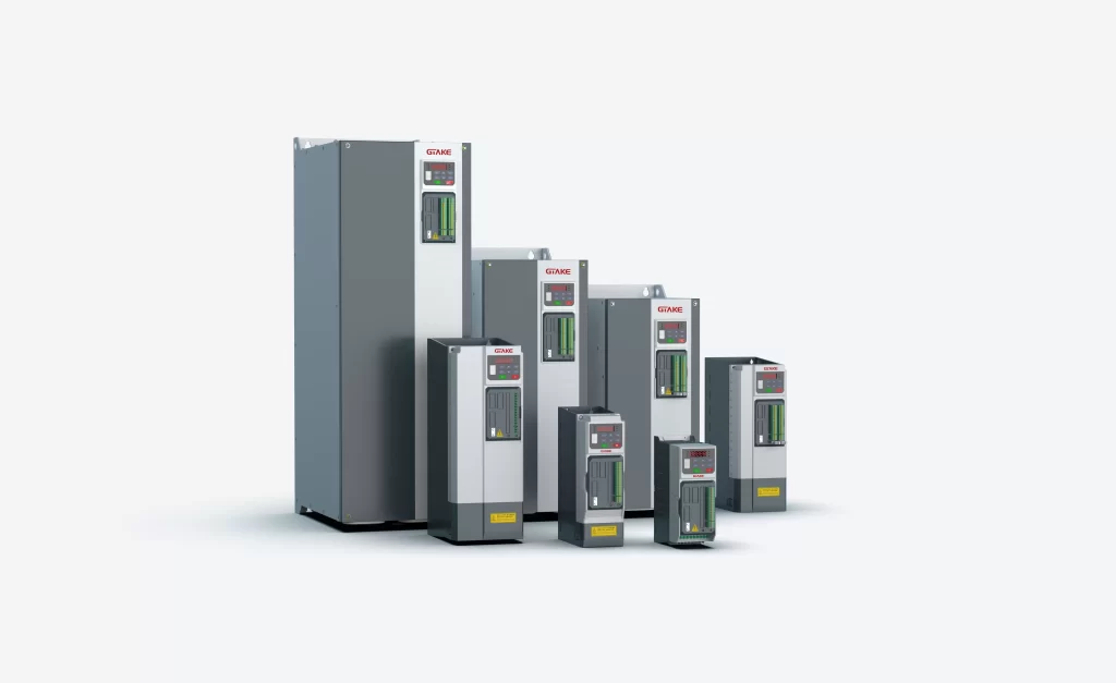
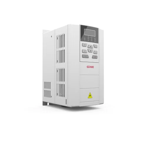
Frequency converter is one of the more widely used devices in the field of industrial speed control transmission. Frequency converter is a device that converts the industrial frequency (50Hz) into various frequencies of AC power supply to realize the variable speed operation of the motor. Among them, the control circuit completes the control of the main circuit, the rectifier circuit converts the alternating current into direct current, the DC intermediate circuit smoothes and filters the output of the rectifier circuit, and the inverter circuit inverts the direct current into alternating current.
Due to the switching characteristics of the inverter circuit, a typical nonlinear load is formed on its power supply, therefore, the power electronic device represented by the inverter is one of the most important harmonic sources in the utility grid.
Harmonics are the components of periodic non-sinusoidal AC quantities obtained by Fourier series decomposition that are greater than integer multiples of the fundamental frequency, usually also called high harmonics, while the fundamental is the component whose frequency is the same as that of the industrial frequency.
As far as the voltage from a three-phase alternator in a power system is concerned, it can be considered that its waveform is basically sinusoidal, i.e., the voltage waveform is basically free of DC and harmonic components. However, due to the existence of a variety of harmonic sources in the power system (harmonic sources are electrical equipment that inject harmonic currents into the utility grid or generate harmonic voltages in the utility grid), especially equipment such as current converters.

Where do harmonics in inverters come from?
1. inverter input harmonic generation mechanism
The main circuit of the inverter is generally a cross has been a cross composition, the external input 380V/50Hz industrial frequency power supply through the three-phase bridge uncontrolled rectifier into a DC voltage, capacitor filtering and high-power transistor switching elements inverter for the frequency of variable AC voltage. In the rectifier circuit, the waveform of the input current is an irregular rectangular wave, and the waveform is decomposed into the fundamental and the harmonics according to the Fourier series, and the harmonic number is usually 6n±1 high harmonics, in which the high harmonics will interfere with the input power supply system. If the reactance of the power supply side is sufficiently small, the overlap angle of the converter” can be ignored, then the nth high harmonic is 1/n of the fundamental current.
2.Inverter output harmonic generation mechanism
In the inverter output circuit, the output current signal is modulated by the PWM carrier signal pulse waveform. For GTR high-power inverter components, the carrier frequency of PWM is 2-3kHz, while the highest carrier frequency of PWM of IGBT high-power inverter components can be up to 15kHz. similarly, the output current signal can be decomposed into only the fundamental and other harmonics.

How to calculate inverter harmonics?
1.Method 1
- Method 1: Fourier transform to get the amplitude and phase of each harmonic of voltage and current, calculate the active power of each harmonic according to P=√3UIcosφ, and add the active power of all harmonics to get the harmonic power.
- Method 2: Measure the total active power, Fourier transform to get the amplitude and phase of the fundamental wave of voltage and current, calculate the fundamental active power according to P=√3UIcosφ, the total active power minus the fundamental active power is the harmonic power. Harmonic power measurement accuracy is low, generally the higher the harmonic frequency, the lower the accuracy, the second method is recommended.
Method 2
- Inverter primary side
The possibility of power voltage distortion is very small, while the possibility of current harmonic distortion is large. The power calculation can be based on
P=U*I1*cosa1.
S=U*I.
PF=P/S=(I1/I)*cosa1.
Can also be based on the definition of THDi, DPF to write a simplified form of this formula; various types of textbooks to write a lot.
- Inverter secondary side
According to Zhou Shouchang, “Principles of Electric Circuits”, “Analysis of Non-sinusoidal Periodic Current Circuits”proved that different harmonics between the voltage and current can not produce power, and its product is 0. Then, in addition to the fundamental power, harmonic power is good to calculate. It can be written Summing symbols (h=1 to ∞) (Uh*Ih*cosah).
At GTAKE, we integrate cutting-edge technologies into industrial variable frequency drives, servo drives, winder power converters, solar inverters for the industrial and clean energy markets. We also offer HEV/EV motor controllers for automobiles with superior efficiency, reliability and passenger comfort. Our growth is driven by the growing demand for better performance of automation systems and energy management, lower emissions and greater intelligence.
